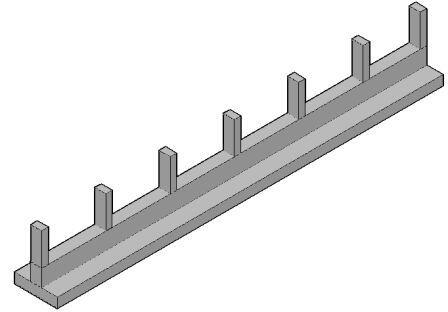
Several types of RC beams - defined with respect to. SK 21 Simply supported beam.

Design Of Continuous One Way Slabs With Excel Worked Example Youtube
ASDIP CONCRETE is a structural engineering software for design of concrete members.

. 3750 150 400Continuous beam design BS 8110 Example 1 A typical floor plan of a small building structure is shown in Fig. EXAMPLE ON THE ANALYSIS AND DESIGN OF CONTINUOUS SLAB AND BEAM FOOTING PER BS 8110-11997. Singly reinforced beam 21.
Design of Reinforced Concrete Beams 20 NOTATION min max. Design of continuous slab and beam footing per bs 8110 1 1997 ubani obinna uzodimma department of civil engineering nnamdi. Design of the footing cantilever slab portion per meter strip Note that the bending moment in the slab is maximum at the face of the column in this case at the face of the upstand beams Width of the upstand beam 500mm 05m.
SHEAR DESIGN BY BS 8110-11997 Design of support A Ultimate shear force at centerline of support V 50046 KN Using the shear force at the centreline of support. 456-2000 in hindicontent cover in this videodesign of con. Amount of reinforcement 3.
October 17 2017. Design for bending M Mu Maximum moment on beam moment capacity of the section The moment capacity of the beam is affected by. - Design is based on British Standard BS 8110-1 1997.
Continuousbeam hindiin this video i will explain about design of continuous beam as per is. SK 23 Cantilever beam. BS 8110 part 01 is one of the most commonly used standard and the method expressed in the code can be understood very easily compared guides given for design of other elements.
Macros must be enabled for proper working of the spreadsheet. Remember me on this computer. 223 Redistribution of moments 2231 Continuous beams.
2016 EXAMPLE ON THE ANALYSIS AND DESIGN OF CONTINUOUS SLAB AND BEAM FOOTING PER BS 8110-11997 Ubani Obinna Uzodimma Department of Civil Engineering Nnamdi Azikiwe University PMB 5025 Awka Anambra State Nigeria E-mail. EXAMPLE ON THE ANALYSIS AND DESIGN OF CONTINUOUS SLAB AND BEAM FOOTING PER BS 8110-11997. Structural Design 1 Lesson 5 5 431 Worked example A simply supported beam has an effective span of 9 m and supports loads as shown.
Design example Design Data Bending Moment 250 kNm Shear Force 200 kN Beam width 225 mm Beam height 600 mm Grade of the concrete 25 Nmm2. Notation for beam clause 3443 BS 8110 b hd d AS AS 19. Design continuous beams 3 AD andB15 assum- ing the slab supports an imposed load of 4 kNm 2 and finishes of 15 kNm 2.
Log in with Facebook Log in with Google. Beam Design to BS 11. The restriction in this free lite version is that you cannot change the company name nor the logo shown in top left corner - currently set to a made.
MASTERSERIES CONCRETE SLAB DESIGN. Depending on the boundary condition and the properties of the slabs methods of finding bending moment is expressed in the BS 8110 Part 01 as follows. Support Conditions - Simply.
The effective depth d 2. Analysis and Design of Continuous Slab and Beam Footing. Coefficients can be used clause 3 4 3 of bs 8110 uniformly loaded continuous beams with approximately equal spans moments and shears.
The first stage of the design is finding the bending moment of the slab panels. About X-X axis as shown in the figure below. Design of continuous beam with simply supported by using limit state design approach.
Normal requirement as per clause 32122 Of BS 8110. 8110 are satisfied design coefficients can be used clause 3 4 3 of bs 8110 uniformly loaded continuous beams with approximately equal spans moments and shears free lite version r c beam design to bs 1 1 the. Close Log In.
SK 212 Continuous beam. RAFT FOUNDATION DESIGN BS8110 PART 1 1997. 11 Introduction This design is.
Reinforcement position and c. Beam Design Bs 8110 Example beam design to bs 8110 singly reinforced section design beam design can be done for different codes depending. A reinforced concrete braced column is 250 mm 500 mm subjected to 1500 KN plus end moments of 8 0 KNm and 30 KNm.
DESIGN OF SOLID SLAB BY SAFE. Design the column if. Structural Design 1 Lesson 5 5 431 Worked example A simply supported beam has an effective span of 9 m and supports loads as shown.
There is two conditions that should be satisfied to use the above table. Hence dimensions of the cross-section is adequate for shear. Strength of steel bars 4.
The design of continuous beams may become cumbersome and time-consuming since it involves the analysis of the beam to find the. TWO WAY SLAB DESIGN EXAMPLE BS 8110 MERMICROBIT SE. The overall sizes of the beams and slab are indicated on the drawing.
The following table can be referred. The columns are 400 400 mm. Determine suitable dimensions for the effective depth and width of.
Shear stress v V bd 50046 10 3 400 543 2304 Nmm 2 v 2304 Nmm 2 08Fcu 4732 Nmm 2. 2-Estimate the maximum Mve and M-ve values We have from statics that M-ve WultL28 where L is the span length. Up to 24 cash back BS 8110 details how deflections and the accompanying crack widths may be.
NOTE 3 For a continuous beam if the percentage of redistribution is not known but the design ultimate moment at mid-span is obviously the same as or greater than the elastic ultimate moment the stress f s in this table may be taken as 23f y. 1-Estimate The Ultimate load for which we have the maximum value of 120 Wd160WL or 140 Wd for the given two-span continuous beam. Follow instructions in this video.
Up to 24 cash back 24 Analysis of singly reinforced beam section 25 Design methodology and 26 Assignment 21 Introduction to Reinforced concrete beams Prime purpose of beams - transfer loads to columns. Full-text pdf example on the analysis and design of continuous slab and beam footing per bs 8110-11997 EXAMPLE ON THE ANALYSIS AND DESIGN OF CONTINUOUS SLAB AND BEAM FOOTING PER BS 8110-11997 Obinna Ranks Ubani - Academiaedu. ASDIP CONCRETE includes the design of multi-span continuous beams based on the latest ACI 318 provisions.
Strength of concrete 20. Based on Table 310 of BS 8110 100 A s prov Factor bd 000 100 015 105 025 108 035 110 050 1. The following steps will be followed to perform the design of a continuous beam.
2Limiting the design shear stress vVbd to say 12N. Earth Pressure intensity q NA prov 18765975 KN 3993 m 2 46997 kNm 2.

Design Of Reinforced Concrete Beams Part 3 Continuous Beams Youtube
Analysis And Design Of Continuous Slab And Beam Strip Footing Structville

Design Of Continuous Beam Using Mdm Civil Engineering Youtube

Design Of Reinforced Concrete Beams Part 2 Design Example Youtube
Design And Calculation Of Monorail Beam Spreadsheet Spreadsheet Design Beams

Solid Slabs Design And Calculations To Bs 8110 1997 Spreadsheet Spreadsheet Slab Design
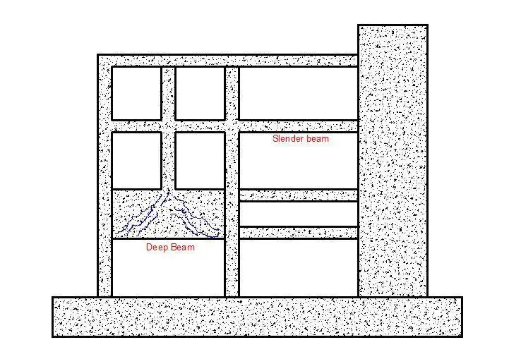
Design Of Deep Beams Structville

Design Of Reinforced Concrete Solid Slabs Part 3 Continuous One Way Slab Worked Example Youtube
0 comments
Post a Comment